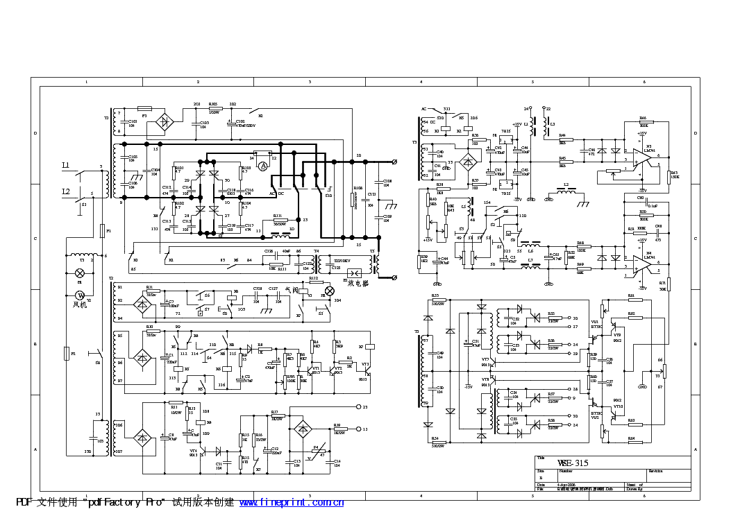
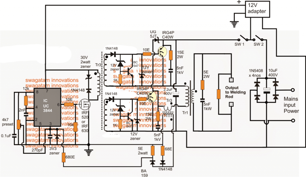
welding inverter schematic diagram
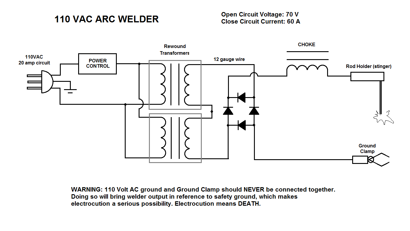
MMA/ARC WELDING A consumable electrode is connected to a high amperage low voltage supply which creates an electric arc between the electrode and the workpiece. PREPARATION To prepare the unit for ARC welding, it is important that you follow the procedure below. 1. Making sure that the ON/OFF switch, lo cated on the rear panel is in the OFF

Easily Understand Inverter Welding Machine with Block Diagram ETechnoG
The diagrams for DC arc welding machines can typically be found in the manufacturer's manual or online. Additionally, many websites offer free PDF versions of the diagrams for those who wish to download them for reference.
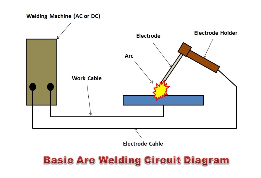
Arc Welding Machine Circuit Diagram
Arc welding is a welding process that is used to join metal to metal by using electricity to create enough heat to melt metal, and the melted metals when cool result in a binding of the metals. Arc Welding Introduction Arc welding is one of several fusion processes for joining metals.

ESAB Arc 200i Inverter Welding Machine, इन्वर्टर आर्क वेल्डिंग मशीन ESAB India Limited
in this video i explained ARC-200 #Inverter #Welding Machine Circuit #Diagram Explained in detail for mma-200, arc-200 igbt / mosfet inverter welding machine.

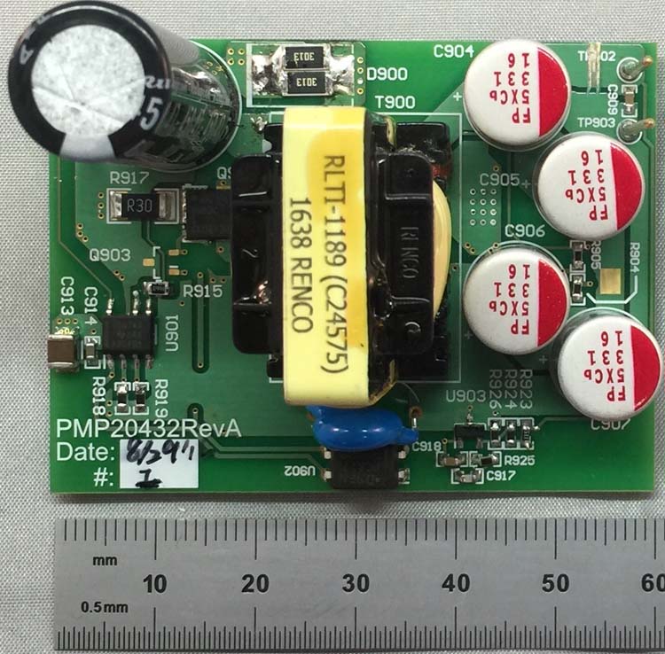
Arc Welding Machine Circuit Board
Welding Machine Schematics Service Manual gevv | February 6, 2020 Updated 9 Comments Circuit diagrams of many welding machines available on the market, even if the brands do not match the model numbers, welding machine service manuals. Some models have the same control, driver floors only IGBT, transformer, etc.

SA 200 Lincoln Welder Parts Understanding and Troubleshooting the Lincoln SA200 DC Generator
Page 1 WELDABILITY ARC200S MACHINE INSTRUCTION MANUAL ® PHONE : (+44) 0845 130 7757 FAX : (+44) 01462 482202 Website: www.weldability-sif.com Email: [email protected].; Page 2: Section 1 : Product And Company Identification PRODUCT USE : MMA "stick" welding applications. PREPARED BY : Technical Support Team, Weldability | Sif SECTION 2 : GENERAL SAFETY CONSIDERATIONS FOR ARC.

Arc Welder Circuit Diagram Service Manual
or severe burns. The electrode and work circuit is electrically live whenever the output is on. The input power circuit and machine internal circuits are also live when power is on. In semiautomatic or automatic wire welding, the wire, wire reel, drive roll housing, and all metal parts touching the welding wire are electrically live.
لحام القوس الكهربائي
A welding machine circuit diagram is a graphic representation of the various electrical components and connections used to power a welding machine. The diagram shows the power source, the welding machine, and the other necessary components such as switches, transformers, and relays.

Inverter Welding Machine Circuit Diagram Pdf
ARC200 Connection Diagram | PDF ARC200 Connection Diagram - Free download as PDF File (.pdf) or read online for free. welding machine ARC200 Connection Diagram welding machine ARC200 Connection Diagram
Arc 200 Welding Machine Circuit Diagram Pdf Wiring Diagram
Download ARC 200 Operating Manual PDF. Cookie Policy This site utilizes cookies to guarantee you get the best experience on our site.
Arc Welding Machine Circuit Diagram Pdf Wiring Diagram
ARC 200 Manuals Manuals and User Guides for ARC 200. We have 1 ARC 200 manual available for free PDF download: Operating Manual ARC 200 Operating Manual (29 pages) Welding inverter Brand: ARC | Category: Welding System | Size: 5.12 MB Table of Contents Table of Contents 10 1-General Remarks 11 Power Source Features 11 Functional Principle 11

Arc 200 Welding Machine Circuit Diagram Pdf
Clean the paint away carefully and tread the bolts. 5. Place the crank handle down over the shaft on the top of the welder, lining up the hole in the crank handle body with the hole in the shaft. Slide cotter pin through the hole and bend the longer end of the cotter pin around the handle. Assembly is now complete.
[DIAGRAM] Diffusion Welding Diagram
4) arc-leading pulse knob is to adjust the welding function, esp. match current knob in little current range, can take convenience to adjust the current of arc-starting, and is out of control of the welding current knob . WELDERS. USERS'MANUAL .ARC SERIAL 04 CIRCUIT DIAGRAM STRUCTURE INV ERT W LD 8 .8 8 . 11 WELDERS. USERS'MANUAL .ARC SERIAL

200 Amp Welding Machine Circuit Diagram
ARC 200 Operating Manual - Free download as PDF File (.pdf), Text File (.txt) or view presentation slides online. ARC 200 Operating Manual

Arc 200 Welding Machine Circuit Diagram Pdf
5.3. MMA electrode holder and earth cable connection (Wiring diagram) Pay attention to the polarity of wiring before MMA welding. Generally, there are two connection methods of DC welder: DCEN and DCEP connection. DCEN: the welding electrode holder is connected to the negative polarity, and the workpiece is connected to the positive polarity.

Welding Machine Schematic Diagram
PS07571 ARC200 Stick Welder Assembly & Operating Instructions Manual 2 GENERAL PRODUCT SPECIFICATIONS SPECIFICATIONS Includes 10-ft. Welding Cable & Electrode Holder 6 1/2-Ft. Ground Cable & Clamp FEATURES: Handles 1/16 in.-5/32 in. Dia. Electrodes 65-200 Amp Welding Range Amperage Indicator Thermal Overload Protection Light Output 25.2V Ac